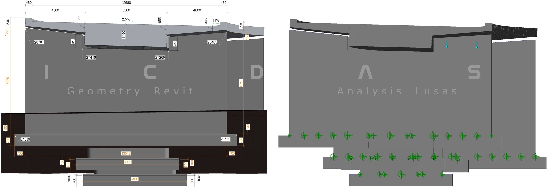
S o f t w a r e     f o r     a u t o m a t i c     c r e a t i o n     o f     m o d e l s     u s i n g     p a r a m e t r i c     d a t a

123456789_123456789_1123456789Concrete Bridge Software 

Models Example
ICDAS COB 2024.00R

Road Bridge Model Examples
  123456789_123456789_123456789_123456789_123456789_123123456789_123456789_123456789_123456789_123456789_123456789_12345
 
123456789_123456789_1123456789123456789_123456789_123456789_123456789_123456789_123456789_12

Concrete Bridge

Model Examples


Model description


Input


BIM model


Analysis model


Landscape model


ICDAS Basis of Design


Workflow of Software


Additional features


Rendering, Animation &
Vitural Reality  


Case study


Subscription 


Technical University of Denmark ♦ DTU Ballerup Campus

Exam project 2015/2016 ♦ Answer Book & Case Study


Motorway Bridge over Savstrup Stream in Jutland Denmark

Terrain  -  Geometry  - Analysis 1 2 3 


Prestressed 4-spans Concrete Slab Deck
ICDAS COB Option 2 (Revit Civil Structures)


Analysis model (1 of 3)


Analysis model as geometry model


Using ICDAS you can create geometry and analysis models on the same time based on the same

ICDAS parametric input, if you are two in the project. ICDAS input contains all information

for LUSAS Bridge.


Only few inputs will be used for Revit since alignment and longitudinal profile are in integration with

Civil 3D (ICDAS will automate the deck cross section, piers, foundations and abutments in Revit,

after integration with Civil 3D).


However, terrain data in Civil 3D must input for LUSAS model. Here the alignment of circle R3500, 

longitudinal slope 2.8% and the cross sectional slopes 2.5% & 11%.


Figure 1
: Geometry model Revit and analysis model LUSAS.

123456789_123456789_1123456789123456789_123456789_123456789_123456789_123456789_12345678123456789_123456789_123456789_123456789_123456789_12345678
  

ICDAS will automate the analysis model accordingly

to the Revit geometry model. The global coordinate

in LUSAS is reset to (0,0,0) at the top right corner of

the deck.


Once dimensions of the bridge changed in LUSAS,

you need to modify it manually in Revit. It can be the

thicknesses of the deck, positions and dimensions of

the piers and the abutments.


Geometry (drawings) and analysis model (static
documentation) must be worked side-by-side.
Open always Revit and Lusas. In Lusas you can
mouse on a line for its length, e.g. the height of a
pier (to update the pier in Revit)
 

FEM model


ICDAS automate the LUSAS model with:


•    the deck curves in circle R3500 with 1m-line-

     element, and thereby 1m2 surface shell element.


•    the deck varying thickness assuming that the

     mesh is located at the bottom of deck (using

     thickness eccentricity)


•    The deck slopes 2.8% in longitudinal direction

     and 2.5% in cross direction


•    3500 load cases incl. single load cases, basic

      combinations, smart combinations, envelopes according

      to Danish Road Directorate April 2015 and Eurocodes.


•    Pier lines position to create the piers manually (will be

      automated in the next ICDAS version)


•    Cable fictive beams preparing for the 5-steps cables

      input


You must ensure the FEM model is corrected before going to
the next step with prestressing cables in concrete deck.


Prestressing cables


The cable geometry is designed in ICDAS Excel and paste in LUSAS manually. The cable geometry, as a combination of parabolic functions and tangents, have also two slopes in longitudinal and cross directions. You can check positions of the cables in the deck (centre box) in LUSAS. We have XYZ position of the cables in LUSAS Presstress Wizard (from Excel) and XYZ points at bottom of deck in LUSAS (also position of the mesh).


Figure 2 shows the cables over the 4 spans in 3D, and
figure 3 shown XY position of the cables at the first two spans.


123456789_123456789_1123456789
Figure 2: 3D model with prestressing cables (blue)


Figure 3: Element mesh and prestressing cables for the first two spans, Top view.


123456789_123456789_1123456789

Static System, bearings and supports


Foundation supports
The foundations are assumed to be fixed support at the

bottom. If the foundations (and the piers) have to be

verified for concrete and reinforcement, then the 

supported spring stiffnesses needed to be calculated

(UX, UY, UZ, RX, RY, RZ).


These values are entered in Supports folder in Attributes

folder in LUSAS. The foundation support conditions donot

significantly affect on the deck, as long the piers are not

too short.  

Pier-deck couplings
There are three types A, B and C of coupling top of piers

to bottom of deck through the bearings in this bridge. The

fixed coupling at the centre pier, A and B for the two side

piers.


At the abutment piers the bearing type A is employed,

and type B apply for the pier no. 2 and 4. The type A the

bearing is locked for motion in transverse UY direction.

The top and bottom plate of this bearing needed to

anchorage to bottom of deck, and top of pier, 

respectively (not shown below).


The bearing's stiffnesses (UX, UY, UZ, RX, RY, RZ) are

entered in Joints folder in Material folder in LUSAS.

These data are from the bearing producers for the

dimensions you choose.


Design of bearings is important since it directly affect on

the deck behaviour under loading. The bearing capacity

vertical forces must be selected after Max/Min results for

ULS load combinations. Refer to ICDAS Design Basis

and the text book Concrete Bridge using LUSAS for

criteria of bearing's displacement and rotation.


123456789_123456789_123456789_123456789_123456789_12345678910


123456789_123456789_1123456789


Figure: Static system of Savstrup Bridge


Terrain  - Geometry  - Analysis 1 2 3  Savstrup Bridge 
   Updated 04-02-2016


123456789_123456789_1123456789ICDAS  •  Hans Erik Nielsens Vej 3  •  DK-3650 Ølstykke  •   E-mail: th@icdas.dk   •  Tel.: +45 60 53 83 79  •  CVR no.: 34436169